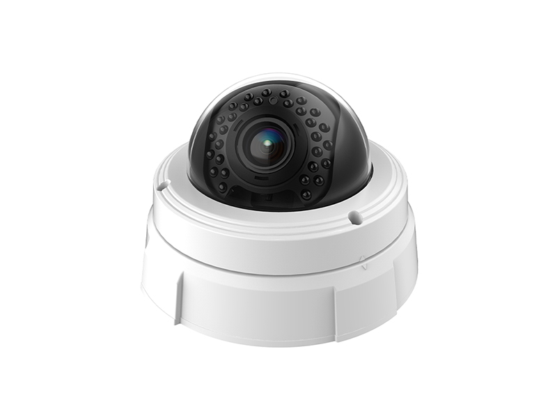

Observation Targets and Mounting Positions
Visibility needs at power and energy sites concentrate on equipment state: busbars and cable joints inside distribution rooms, switchgear panels and instruments, transformer housings and cooling structures, battery rooms and cable-trench entries. These positions are poorly lit and entered infrequently, so keeping the picture at a remote point is less effort than a site visit each time. The thermal imaging channel adds the temperature distribution layer, and the visible-light channel carries equipment appearance and meter readings.
Mounting positions must balance measuring distance and angle of view. A thermal channel looks at the measured surface, so the distance from camera to busbar, the lens focal length and the size of the measured area have to match: too far and a single-point temperature covers adjacent structure, so the reading loses reference value; too close and the field narrows, so one inspection round covers only a single row of cabinets. Where cabinet rows run long, cover them in segments with two or three units rather than scanning wide with one, which resolves joints better.
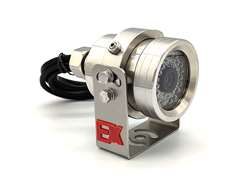
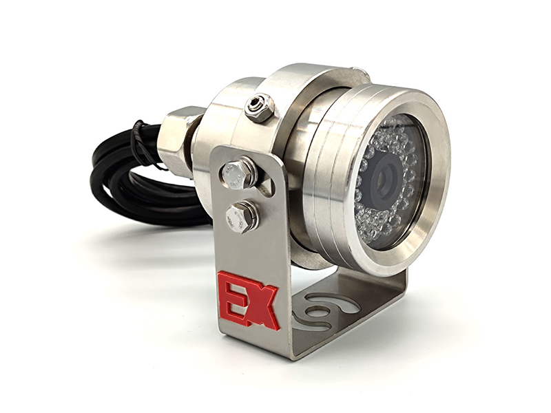
Outdoor and harsh positions are selected by protection and weathering requirements, with an IP-rated enclosure where needed, and explosion-proof network cameras where flammable gas or dust may be present, following the site's own safety rules for mounting method and point spacing. The temperature observation and visual coverage described here do not replace professional electrical testing or relay protection trials; the specific finding is made by the operator per their procedures.
Front-End and Recorder Equipment
Assign channel types by the measured surface, and plan retention periods for thermal imaging and visible-light channels separately.
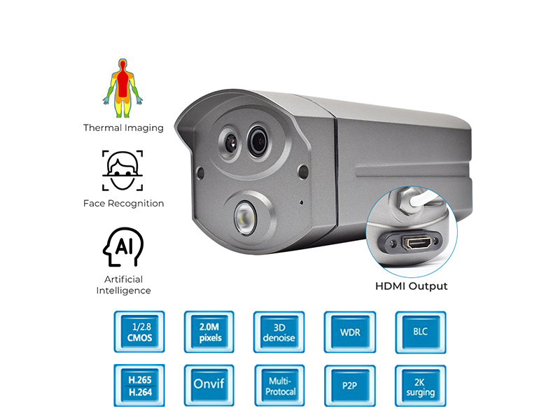
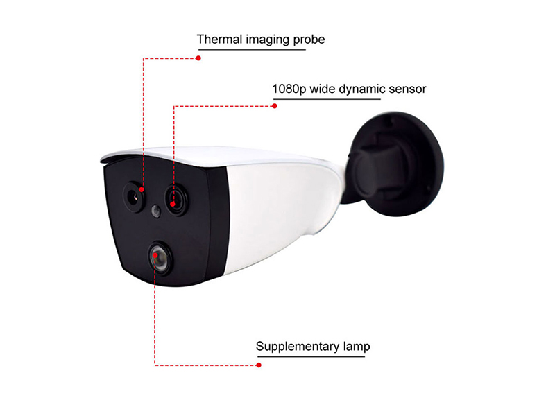
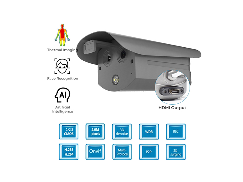
- Distribution rooms and switchgear areas: dual-spectrum thermal imaging camera comparing thermal and visible-light pictures in one frame
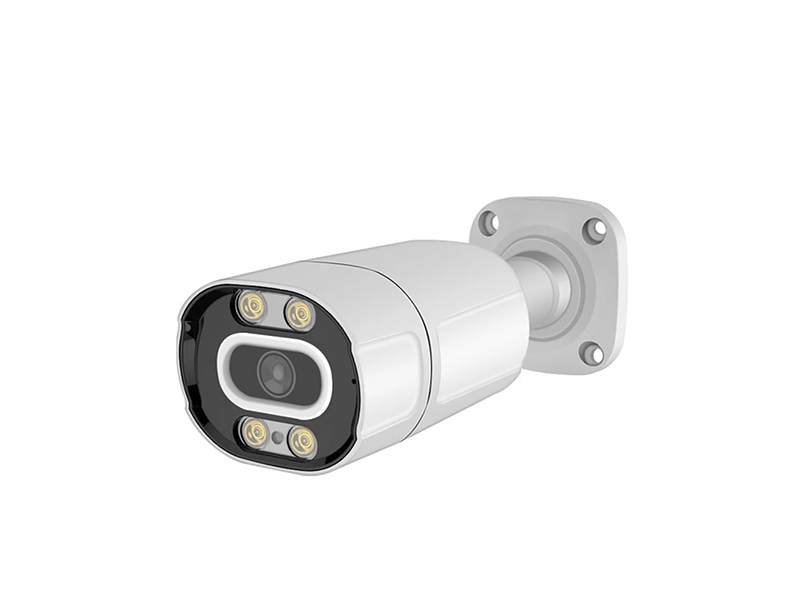
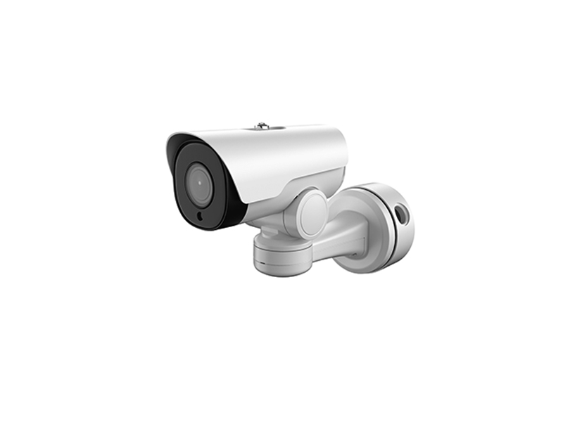
- Long busbars and transformer bodies: motorized varifocal network bullet camera for appearance, thermal camera for temperature distribution
- Positions needing reading verification: thermal camera with a blackbody reference so the frame keeps its own reference
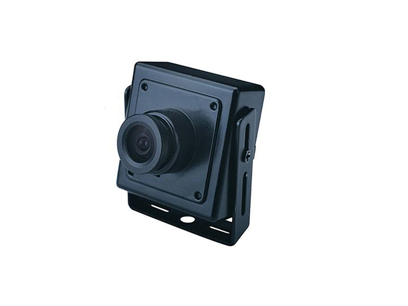
- Cable trenches and narrow shafts: miniature network camera filling in visual points, powered by PoE to reduce wiring
- Recorder side: a network video recorder that accepts thermal imaging channels, with temperature and video sharing one time axis
- Field commissioning: confirm output form and video format per channel with a CCTV tester and a laptop before installation
Connection and Installation Points
Connecting thermal equipment is stricter than ordinary surveillance about output form and mounting stability, because a shifted position invalidates every preset inspection area.
| Step | Practice | Equipment used |
|---|---|---|
| Output integration | Send HDMI-output thermal cameras through a video encoder into a network stream, or into an inspection workstation via a capture card | Video encoder, video capture card |
| Point fixing | Use rigid brackets and retighten after construction so vibration cannot drift the measured area slowly | Video and audio accessories |
| Reference setup | Place a blackbody or equivalent reference inside the frame so readings taken at different times can be compared side by side | Thermal imaging camera |
| Field calibration | After installation, record measured areas cabinet row by row into a point-and-area comparison table | Dual-spectrum thermal camera |
| Environment fit | Choose the matching IP-rated model for outdoor and dusty positions, and watch for lens fogging caused by temperature difference | Network camera |
Recording, Bandwidth and Temperature Records
Budget visible-light channels at 2 to 4 Mbps per 1080P channel and 6 to 8 Mbps for higher-megapixel channels, then calculate the thermal channel bitrate separately from its resolution and frame rate, setting different retention for the two channel types on the same recorder. Temperature data serves trend recording and after-the-fact replay, so its retention usually runs longer than ordinary security channels and follows the site's maintenance cycle.
- Put temperature channels and video channels on one time base so picture and value align in replay
- Recalibrate whenever a measured area changes rather than reusing the previous preset
- Keep remote viewing on the substream and reserve the main stream for local archive, protecting site uplink bandwidth
- Treat alarms only as prompts; the finding follows the site's own testing and operation procedures
Inspection Workflow and Picture Review
Remote inspection runs in two steps: read the thermal channel first for temperature distribution and relative difference across the measured surface, then switch to the visible-light channel to check equipment appearance, meter indication and switch position. Only replaying both channels on one time axis matches temperature change with field operation, and keeping a single channel loses that comparison. When a distribution looks abnormal, arrange operations staff to verify on site with the station's own instruments, because the picture is only a trend record and review basis, and the site's testing procedures decide the finding. If maintenance or a cabinet move changes a measured area, recalibrate the area range and update the point table, since old presets read unusable values against a new layout.
- Fix the inspection order within a shift and compare cabinet row by row rather than at random
- Write temperature records and video records into the same maintenance log for later traceability
- Keep the reference position inside the frame, and mark any session where it was obstructed as not comparable
- Clean a fogged or fouled lens before reading anything, and never treat contamination as a temperature anomaly
- Recheck night pictures at season changes, since light conditions and temperature difference both affect the visible-light channel
Delivery and After-Sales
Delivery includes the point-and-measured-area table, the output form table and the equipment list, confirming per channel that the view is fixed, the picture clear, and recording and time sync working, then transfers after one week of continuous operation without faults. Products ship to Europe, the Americas, the Middle East, South-East Asia, Australia and Africa, with every finished unit fully inspected on our own production line and support for structure, silk-screen marking and preset firmware parameters. Send the distance from position to measured surface, the switchgear row length, the thermal device output form and the target recorder brand and model to info@vctcctv.com, and we can ship samples with a compatibility list first, or call +86-755-28146081 to arrange remote guidance.