
A loop voltage-drop formula for centralised DC 12 V supply, a far-end voltage table by conductor gauge and length, the boundary between PoE 802.3af and at, and how to size power margin.
How the Two Supply Methods Are Written in Parameters
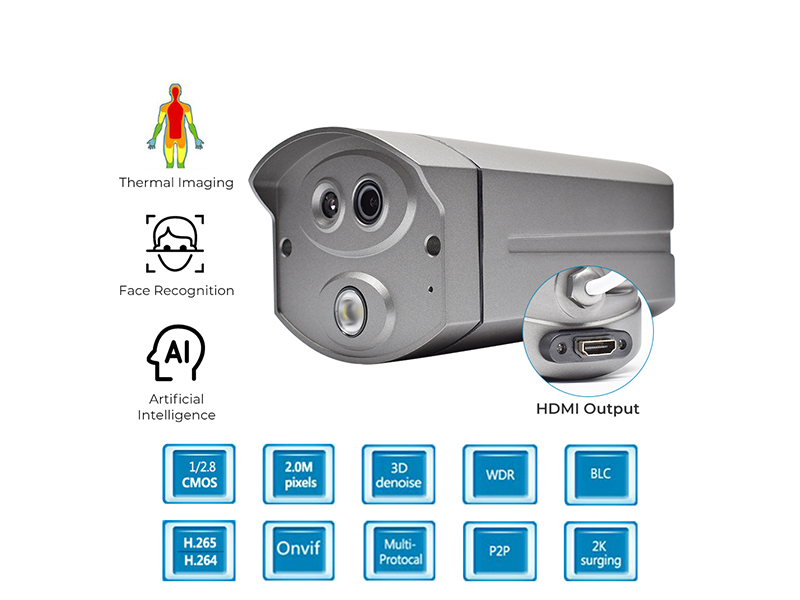
Two notations dominate the power row of network front ends here: DC12V±10% and PoE 802.3af. The 3MP starlight waterproof bullet, the 8MP AI starlight fixed-focus bullet, the 12MP AI vandal-proof dome and the 3MP and 5MP starlight explosion-proof network cameras all carry both labels, with unit consumption under 5 W. The PoE supply version of the 5MP micro network IP camera is labelled DC12V±10% plus PoE, also under 5 W, in a Φ25×80 mm body.
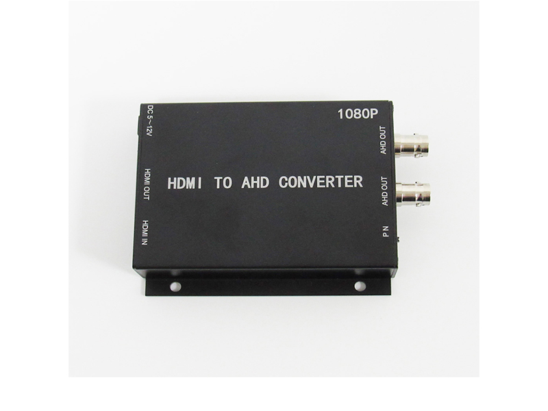
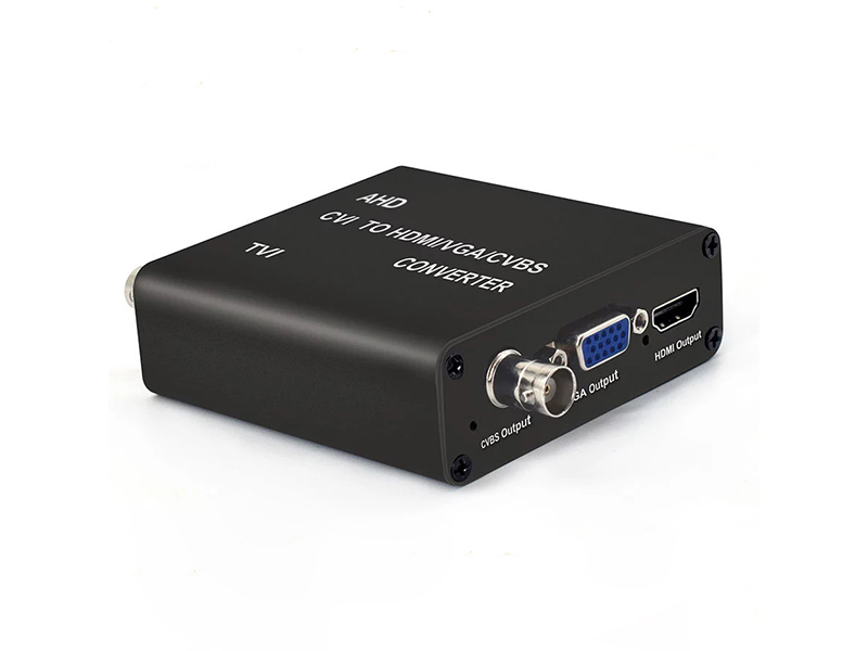
DC-only labels cluster on encoders and micro coaxial cameras. The 2MP AHD/TVI/CVI to IP video encoder takes DC12V 1A and draws about 1 W. The H.265 1080P HDMI network encoder takes DC12V 1A and draws no more than 3 W, and its PoE version adds power over ethernet. The body-temperature face access recognition camera is labelled DC12V 3A with a maximum consumption of 20 W, which makes it a high-draw device that must be fed locally. These figures are the inputs for any power calculation.
The Loop Voltage-Drop Formula
Voltage drop under centralised DC supply turns on one thing: the round-trip resistance of the line times the working current. Write it as R equals 0.0175 times 2L divided by A, where L is the one-way length in metres, A is the conductor cross-section in square millimetres, and 0.0175 is the copper resistivity constant. Current I equals device consumption divided by 12 V. The pass line is the lower bound printed on the product: DC12V±10% means the far-end voltage must not fall below 10.8 V.
The table works out common configurations in volts. Every value is the far-end voltage with the power supply output at 12.0 V. Combinations below 10.8 V fail and call for a thicker conductor, a shorter supply run, or local take-off.
| Device consumption | Supply cable length | 0.5mm² | 1.0mm² | 1.5mm² | 2.5mm² |
|---|---|---|---|---|---|
| 5W (about 0.42A) | 50 m | 10.5 V fail | 11.3 V pass | 11.5 V pass | 11.7 V pass |
| 5W (about 0.42A) | 100 m | 9.1 V fail | 10.5 V fail | 11.0 V pass | 11.4 V pass |
| 10W (about 0.83A) | 50 m | 9.1 V fail | 10.5 V fail | 11.0 V pass | 11.4 V pass |
| 10W (about 0.83A) | 100 m | 6.2 V fail | 9.1 V fail | 10.1 V fail | 10.8 V at the limit |
| 20W (about 1.67A) | 50 m | 6.2 V fail | 9.1 V fail | 10.1 V fail | 10.8 V at the limit |
| 20W (about 1.67A) | 100 m | All below the lower limit: feed locally or switch to PoE | Same as left | Same as left | Same as left |
Capacity Headroom on a Centralised Supply
Size a centralised supply by summing front-end consumption and multiplying by a factor of 1.3 to 1.5, and include the current step when the IR illuminators start. A DC12V 2A supply carrying network bullets under 5 W supports four channels in theory, but with the headroom factor you take three. Once IR engages at night, instantaneous per-channel consumption rises, so one channel fewer is the safer choice.
When several points share one supply cable, total current matters as much as drop: the far-end voltage equals the supply output minus the accumulated drop across the whole trunk and its branches, and the camera nearest the end of the run absorbs the largest drop. In practice put high-draw equipment at the trunk start and low-draw equipment at the far end, and never hang a 20 W access terminal and an end-of-line bullet on the same cable.
Where PoE Applies and What to Check
Power over ethernet carries electricity and data on one Cat5e or Cat6 cable, with a single run kept within 100 m by normal ethernet cabling practice. An 802.3af port budgets 15.4 W to the powered device, so bullets, domes and micro cameras under 5 W leave close to three times the headroom. When you must feed high-draw PTZ domes or equipment with heating structures, budget against 802.3at instead. Every network camera labelled PoE 802.3af here also lists consumption under 5 W, which matches the af budget.
Run the checks below on site. Any single failure shows up as repeated reboots or night-time dropouts.
- Use oxygen-free copper Cat5e or Cat6; copper-clad steel makes drop and heat uncontrollable over distance.
- Terminate RJ45 plugs fully with a consistent pinout, and measure and record whether both ends negotiate gigabit or 100 Mbps.
- Route network cable and power cable in separate bundles, and avoid long parallel bundling that induces interference.
- Check the switch's per-port budget and its total budget together; throttling ports at full load reboots the front ends.
- Before installation, run the RJ45 TDR cable test on a CCTV tester and confirm link length and breakpoint position.
- Do not force DC-only high-draw equipment onto long PoE splitter feeds; take power locally instead.
Choosing Between the Two Methods
For a new network system with every point within 100 m of the equipment room, use power over ethernet: it removes the power cabling and the centralised supply as maintenance points. In a retrofit that keeps coaxial wiring, front ends stay on DC12V, encoder and converter supplies go nearby, and voltage drop is checked against the table above. For scattered points that total only two or three channels, separate DC adapters control far-end voltage better than one centralised supply.
Mixed systems carry both methods at once. At acceptance, log the measured far-end voltage or the powered port of every channel in a table, and put any run below 10.8 V on the rectification list. Do not judge supply adequacy by whether the picture looks normal.
Data to Provide
Send each device model and consumption, the actual length and gauge of the supply cable or network cable, and the output rating of the centralised supply to info@vctcctv.com, or call +86-755-28146081. We recheck the headroom with the same formula and recommend a conductor gauge. WhatsApp on the same number is available for site communication on export projects.