
Following PoE supply, this covers how cable length, line resistance and ambient temperature change the voltage at the camera, and how to finish measured checks before delivery.
Two Power Methods and the Baseline Draw
Network cameras are powered two ways: a local DC supply or centralized supply over the network cable. The specification of the 5MP miniature network model reads DC12V plus or minus 10% alongside network-cable power, with the whole unit drawing below 5 W; the series' miniature model pairs an FH8852EV200 with a 1/2.9 inch GC4653 photosensor, reaches 2560x1920 maximum, encodes video as H.265 and H.264, and runs a bitrate range of 64K to 2048Kbps under H.265. Power figures start the calculation: fix the unit's maximum draw first, then check whether the supply end covers it.
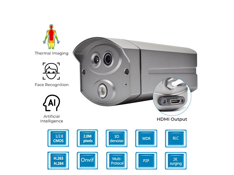
Power-over-Ethernet classes follow the published PoE standards, with two common port budgets of roughly 15 W and 30 W, and cable loss still comes off that at project level. When choosing switch ports, calculate from the unit's maximum draw plus margin and do not look only at the nominal average figure: the inrush current when IR illuminators light up is above average.
The Quantities behind Voltage Drop
The drop is decided mainly by three things: the DC resistance of the conductor, the run length and the ambient temperature. Smaller copper conductors mean larger resistance per unit; as length grows, the resistance of both legs rises together; higher temperature increases conductor resistance. Sites often add connector oxidation and patch-panel jumper cords, segments that are easily ignored. Calculate each segment separately, switch to patch panel, patch panel to outlet, outlet to camera, then total them.
The judgment standard is keeping the actual voltage at the camera inside the machine's allowed input range. On a DC12V plus or minus 10% model, the allowed terminal window is narrower than the adapter's nominal value, so line design must be verified against the least favorable point, not the shortest cable. Long segments and circuits with many series connections are calculated on their own, and the results go into the ledger together with measured values.
Measured Checks before Delivery
Measurements walk the points, following the site rather than the drawing. A CCTV tester with digital multimeter functions measures line resistance and continuity directly on site, and the cable tracing function confirms pairing inside the same bundle. The test record carries position number, cable length, conductor specification, switch port number and measured terminal voltage, forming one ledger page handed to the accepting party.
When measurement shows low terminal voltage, the common order of handling is to shorten the run or reduce series segments first, then switch to lower-resistance wire, and only then consider local supply, such as moving the power adapter to the outlet side or using a locally powered DC model. After any adjustment, retest and update the record, mark the changed location on the routing drawing, and hand it to the operating party together with the ledger at delivery.
Cabling Control Points
The items below are checked repeatedly through the delivery stage, printed on the construction briefing sheet and ticked per position, each ticked item signed by the person who filled it. Positions that fail join a second-verification list without blocking acceptance of other points; the record closes only after second verification, which keeps one issue from circulating between two crews.
- Register each position's actual cable length after measurement, never an estimate
- Conductor specification stays consistent within a batch; mixed cable is not used on one circuit
- RJ45 plugs and patch-panel modules are crimped to standard practice and continuity-tested
- Switch port margin is calculated from the unit's maximum draw, checked separately for IR models
- Long-distance points prefer local supply, with the measured terminal voltage in the ledger
- Runs in high-temperature environments are routed apart from AC power cabling to cut added temperature rise
Selection and Spare Support
Miniature network models, outdoor waterproof bullets and explosion-proof units differ in power draw and supply method, so mixed projects need a supply plan listed by model. For outdoor models rated IP66 and above, the waterproofing practice of the power connector is noted on the same list. To confirm supply parameters, request the measurement record template, or stock power supplies and patch cords as after-sales spares, email info@vctcctv.com or call +86-755-33130307 with your run lengths and port allocation.